
Charles Holford writes:
I am fortunate to own an early 1935 Nippy. I have looked at a number of others at shows and rallies. No two are the same but perhaps that is to be expected, as not one is younger than 82/3 years old. While there are many minor differences to be found there does seems to be a wide variety of horns fitted to these cars. That is not surprising as many owners like a particular kind of horn to look at or for its dulcet tones, but what did Lord Austin fit original to the 65/Nippy?
The Austin 65/Nippy parts booklet states that a Lucas Alto horn was fitted. However, according to the Guide by Chris Gould he has only seen New Alto horn actually on cars. Presumably there must have been an Alto Horn for there to be a New Alto. When it was first made is unknown to me. Perhaps readers can help? Maybe one of you has an original “Alto”, not a ”New Alto” horn fitted to your car? Please let us know and we can add images here.


New Alto horns are high frequency (HF) horns and have part numbers beginning with HF7, for example HF728 or 736 if they are pre-Second World War. Post-War the number began HF1 followed by the number 728 etc. There were 6 and 12 volt versions and I believe high and low tones. Most had a black paint finish on the body and bezel but some had a chrome bezel, chrome domed nuts to fix the bezel and a chrome nut to fix the centre disc to the diaphragm.
The disc is prone to corrosion because it is made of magnesium alloy (certainly for post war Altos) which is a soft metal and easily damaged by chemicals, hence the painted finish to protect it. Why magnesium alloy? Because the type of metal alters the tone and magnesium provided what Lucas considered the “right” tone. The high and low tone depends on the thickness of the steel diaphragm to which the disc is attached. There is a good article on New Alto horns fitted to Jaguar XK140 by” bobine.nl Alto” which explains how they work and how to repair them. Much of what is there applies to pre-war New Altos.
The picture of the Alto horn in the Nippy parts list is a drawing, not a photograph, which makes it difficult to visualise the horn and the mounting bracket for the Nippy. On an MG M type forum website I found a picture of a similar looking bracket and also access to a Lucas parts and service catalogue for 1930-39. Low and behold, there are 42 Lucas horn mounting brackets listed and the bracket part number for the Nippy (and I think for the MG) is 700369. (see photograph)
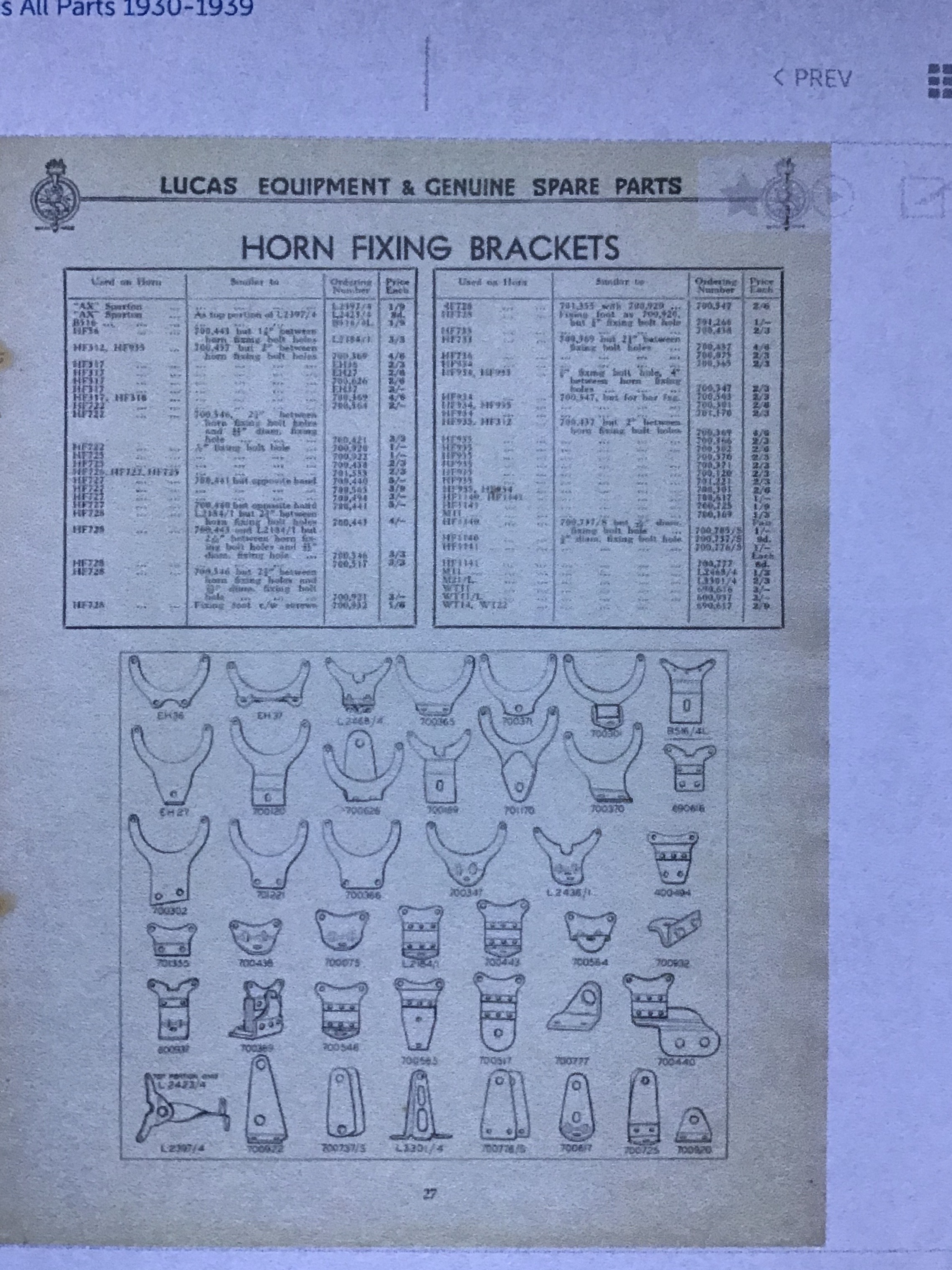


Later I was able to source a 700369 which was original and another that had been “restored”. The photograph shows it to be an angle bracket to which is riveted a short length of rubber strip reinforced by layers of fabric. At the lower end are two crescent shaped flanged bracket in mirror image shaped to form a trough into which the rubber strip is inserted and riveted in place. 

The angled bracket extends downwards in front of the rubber strip to a 5/16th inch hole at the lower end that holds a rubber grommet to act as a “bump-stop”. I believe this was designed to prevent the horn from swinging backwards and forwards under the “G” forces of rapid acceleration and hard braking, well known characteristics of driving an Austin Seven Sports 65 or Nippy!


The 700346 restored bracket that has nuts and bolts, not rivets, fixing the rubber strip has had the original rivets drilled out, a new rubber strip inserted and the rivets replaced with 6 BA Pan-head bolts and nuts. In many cases when the rubber perished or became brittle these brackets were thrown away so they are now uncommon. Drilling out the rivets neatly and without damage to the parts is not so easy but is a very reasonable modification as it has made it possible to replace the rubber strip when necessary. 4 BA roundhead bolts would look better being about the same size as the original rivet. Please also note this replacement rubber strip in the restored bracket is a fraction too short as the hole for the bump-stop rubber does not contact the flanged plates in the right place. The bump-stop plate end is to low being below the crescent edge. The original unrestored riveted bracket may be a little at fault because the rubber strip has stretched a little but is close to the correct position.


I had no idea what was the original orientation of the bracket and horn when bolted together but fortunately Chris Gould sent me photographs of the horn and bracket that came with his car but were not fitted to it when he purchased it in 1961. We believe this is an original horn and bracket but these things can rarely be proved so and corroboration would be very useful. Do any other Archive members have the same arrangement? Please let us know if you have or have something similar.

The photographs show the bracket with the bump-stop facing forwards and the horn bolted to it with a longer bolt than the others on the horn rim (bezel) and a spacer sleeve to create a gap which prevents the bump-stop from contacting the horn. The bezel is also cut away to create more clearance.
Chris has kindly provided me with the following information:
The two bolts that fix the horn to the mounting bracket are 1 and 1/8 inch long measured from below the Fillister head, which could be 1BA. They have a strange thread, not BSF, or metric, about 5mm diameter. We need to find out! The spacers are square being 11/32nd inch (8.731mm) each side and ½ inch long. The hole along the length of the spacer is 17/64th inch
I do not know the model number for this horn, nor do I know the depth or length of the cut away on the horn bezel. Can anyone help? Usually New Alto horns pre-war had an HF7 number stamped on the circumferential flange of the bezel e.g. HF722, Hf7228 or HF7236. Whether the Alto horn had the same number system is also unknown to me or even if it ever existed but as mentioned earlier there should be one for its presumed successor to be the “New Alto”.
Do any of you have knowledge or documentation to help sort this out? Please let us know.
Thanks to Charles. Please let us know if YOU have potential texts on your explorations to upload here. This resource is a share in which we must all play our bit, however small.
Addendum from DKJ 851:
There was indeed an “old” Lucas Alto horn (photos below), an expensive & nice quality item by all accounts and available through the 1920’s and 30’s (no precise dates, sorry). The “New” Alto was launched in 1930 so it seems improbable the original Alto was ever used on the Nippy or ’65. As Charles states, pre-war “New Altos” have a type number beginning HF7, conveniently distinguishing them from later models. A considerable number of variations were produced with different terminal arrangements, threads and materials. I’m afraid I don’t know which was original fit for the Nippy. Info source: “Taff The Horns”.
n.b. Taff has now retired, but passed all his stock to Terence Jones (terrybinns1957@gmail.com) who may well be able to help restorers with spare parts, gaskets or even complete horns.


By my measurement the filister head screws which hold the horn together are 5.3mm OD x 28 tpi which would make them 1BA or at a pinch 7/32″ BSF.
